OneCad Pty Ltd
3D Structural Steel Detailing
Drawing Packages
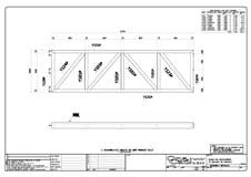
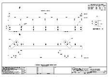
Structural Steel Shop Drawings
All of our shop drawings are extensively checked to ensure that they are error free.
This includes interrogating the 3D model prior to producing shop drawings to ensure:
1. There are no steel clashes and
2. There are no bolt access problems
Once drawings are produced, each one is individually checked and edited to ensure that it is clear and concise.
This includes:
1. Re-dimensioning drawings as required to improve legibility.
2. Adding additional sections or blow-ups as required to provide extra detail.
3. Adding revision letters, descriptions, and clouding to all revised members and GA’s.
4. Adding a description of each member to the title block.
5. Adding a member prefix to all steelwork members to aid in identification and erection.
6. Adding a material finish to each member and assembly drawing.
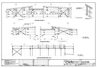
Detailed general arrangement drawings (GA’s) are produced to facilitate site erection.
These are fully dimensioned and show all member erection marks and locations.
These include: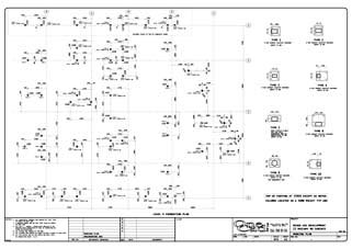
Detailed foundation or HD bolt layouts.
Elevations (including anchor bolt locations if required).
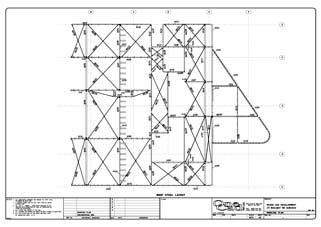
Steel plan layouts.
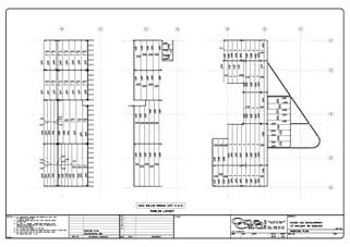
Purlin and bridging layouts.
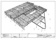
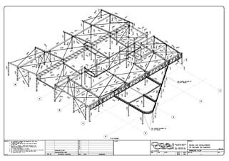
Isometric and perspective 3D views.
Material Cutting and Location Lists
Multiple material lists are produced to provide details on total weights, areas, bolt locations, bolt quantities and for cutting. These are fully customizable to suit your project.
We can also provide StruMIS data for use in the StruMIS management sytem, NC & DXF data for automated cutting/drilling, as well as wrap-around templates as required.

